 Creating retaining walls
|
Command |
Workspace: Path |
|
Create Retaining Wall Site Modifier |
Architect: AEC > Terrain Landmark: Landmark |
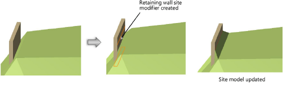
A retaining wall site modifier can be created based on existing walls created with the Wall tool. The existing wall can be a single wall or a chain of multiple wall segments that are L-joined to each other. The retaining wall created can modify the site model, and the terrain can be sculpted around the retaining wall.
Once created, the retaining wall site modifier is not associated with the wall object used to create it.
To create a retaining wall site modifier:
Select the wall or multiple, L-joined walls.
While walls are typically used as the basis for creating a retaining wall, other valid selections include a hardscape object or an extrude object.
Select the command.
The Create Retaining Wall Site Modifier dialog box opens. Set the initial location of the site modifiers within the retaining wall. There are three distinct areas that can modify the site model:
The pad at the bottom of the wall, which can be offset from the top or bottom of the wall, or simply follow the terrain
The left and right side edges of the wall, which can be offset from the top or bottom of the wall, or follow the terrain
The starting and ending edges of the wall
The left and right sides of the wall are determined by the wall direction as it was drawn.
Click to show/hide the parameters.Click to show/hide the parameters.
|
Parameter |
Description |
|
Diagram |
This wall schematic shows the location of the pad modifier at the bottom of the wall (1), the left (2) and right (3) edge modifiers, and the start (4) and end (5) edge modifiers; it also shows the wall start and end, which determines the wall direction and therefore which edge is left and right |
|
Pad |
Specifies the vertical offset and shape of the modifier pad; the modifier can be offset from the top or bottom of the wall and follow top or bottom wall peaks, or can simply follow the current terrain. The pad offset can control the cut and fill values produced by the site modifier. |
|
Offset Below Wall Top |
Sets the pad modifier to be offset below the top of the wall by the specified value |
|
Follow Top Wall Peaks |
The modifier shape follows the wall peaks at the top of the wall. If a wall has vertical peaks, the modifiers will be nearly vertical. |
|
Offset Above Wall Bottom |
Sets the pad modifier to be offset above the bottom of the wall by the specified value |
|
Follow Bottom Wall Peaks |
The modifier shape follows the wall peaks at the bottom of the wall. If a wall has vertical peaks, the modifiers will be nearly vertical. |
|
Follow Terrain |
The pad modifier follows the terrain location (offset and shape) along the bottom of the wall |
|
Side Edges |
|
|
Left/Right Modifier Edge |
Select whether to create the edge modifier objects on the left and/or right sides of the retaining wall. Edge modifiers sculpt the terrain at the left or right of the retaining wall sides according to the parameters set. The modifier can be offset from the top or bottom of the wall and follow top or bottom wall peaks, or can simply follow the current terrain. |
|
Offset Below Wall Top |
Sets the edge modifier to be offset below the top of the wall by the specified value |
|
Follow Top Wall Peaks |
The modifier shape follows the wall peaks at the top of the wall. If a wall has vertical peaks, the modifiers will be nearly vertical. |
|
Offset Above Wall Bottom |
Sets the edge modifier to be offset above the bottom of the wall by the specified value |
|
Follow Bottom Wall Peaks |
The modifier shape follows the wall peaks at the bottom of the wall. If a wall has vertical peaks, the modifiers will be nearly vertical. |
|
Follow Terrain |
The edge modifier follows the terrain location (offset and shape) along the side of the wall |
|
Start/End Edges |
The start and end edge modifiers define how the terrain wraps around the retaining wall sides |
|
Include Start Modifier Edge |
Select whether to create an edge modifier object at the starting edge of the wall |
|
Include End Modifier Edge |
Select whether to create an edge modifier object at the ending edge of the wall |
The original wall remains in the drawing; the retaining wall site modifier is a new, separate object.
Update the site model to apply the changes (select the site model and click Update from the Object Info palette).
Editing retaining walls
Retaining wall parameters can be edited from the Object Info palette.
Click to show/hide the parameters.Click to show/hide the parameters.
|
Parameter |
Description |
|
Apply To |
Select whether the retaining wall modifies the existing or proposed site model |
|
Width |
Determines the distance between the left and right edges of the retaining wall |
|
Pad Offset |
Specifies the offset of the pad from the Z elevation of the retaining wall site modifier object itself; the offset can control the cut and fill values produced by this site modifier |
|
Include Left/Right/Start/End Modifier Edge |
Toggles the modification of the site model by the selected modifier edge parameters |
|
Vertex parameters |
Edits the path vertices; see Editing vertex-based objects |
|
Move |
Select the portion of the retaining wall modifier to edit, and then edit its Elevation, or scroll through its vertices with the left and right arrows and change the selected vertex Elevation |
|
Edit |
For vertex selections made in Move, scrolls through the vertices, highlighting the currently selected vertex. Click the center button to highlight the selected vertex. |
|
Elevation |
Sets the elevation of the modifier item selected in Move or the vertex selected in Edit |
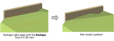
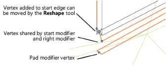
The retaining wall site modifier consists of four modifier edges, joined by common vertices. The left and right edges of the retaining wall site modifier can be reshaped with the Reshape tool (see 3D reshape modes). Move vertices, and add or delete vertices to reshape the retaining wall.
The start and end edges cannot be directly edited with the Reshape tool. However, a vertex added to the left or right edge can be edited by the Reshape tool (select Start/End Modifier Edge from the Move list in the Object Info palette, and click Add Vertex). Adding vertices to the start and end edges allows them to be reshaped.
The Send to Surface command can be used to send either the retaining wall modifier edge or the pad to the surface of the site model.
